Date: 2018.09.10 Views: 2079
INSTRUCTION OPERATION MANUAL FOR FLOATING SPLIT BODY BALL VALVES
1. Forewords
1.1. The valves described in this manual have been designed to block the flow for ON/OFF service only. Do not use the valve for flow control neither in partly open nor for throttling service to avoid damage on the sealing surfaces.
As a type of pressure equipment, valve has potential hazards of pressure and creation of explosive atmosphere resulting from leakage of process fluid. For the safety purpose, user shall read this instruction to know what TSV has already taken into account in our design and manufacture, and what action shall be taken by user according to essential health and safety requirements.
2. Essential health & safety requirements and solution
2.1 What’s TSV design idea
- Ball valve is designed to API 608, valve has adequate strength according to ASME B16.34 pressure temperature rating.
- Valve is designed with fire-safety structure certified in accordance with API 607.
- Valve contains no light metal (such as Mg) and all parts are electricity conductive and connected to prevent ignite resource.
- Valve is designed with hand wheel, or gear operator or electric actuator according to its size and torque, and operation requirements.
2.2 What action user shall take
2.2.1General 2.2.1.1In any occurrence, first ensure personnel safety.2.2.1.2 Use the valves in accordance with ASME B16.34 pressure-temperature rating.
2.2.1.3 Make sure that the selected valve materials are corrosion/wear resistance to the service fluid.
2.2.1.4 Where the service fluid is flammable/explosive, to limit the working temperature.
2.2.1.5 When performing Repair/maintenance operations, make sure that the valves are always depressurized, vented and drained.
2.2.1.6 For actuator operated valves, make sure all supply lines (Electrical, hydraulic, Air) are disconnected before starting any operation.
2.2.1.7 When performing Repair/maintenance operations, always use appropriate protection e.g. protective clothing, (oxygen) masks, gloves, etc.
2.2.1.8 When performing Repair/maintenance operations, do not smoke, do not use any portable no-Ex-proof electrical device in the area and do not use open fire without a valid work permit.
2.2.1.9 Valve must periodically checked on:
- Tightness of bolted connection (body/closure, gland, flange connection).
- Corrosion/wear damages (crack, pitting, thickness of the valve).
- Make sure the valves are in fully open/fully closed position.
2.2.2Specifics|
Risk |
Preventive Action |
|
Accidental contact with dangerous service fluid* Due to: Gasket or Stem Blow out |
1. See2.2.1General |
|
2. Immediately replace Gasket and packing after a Blow-out (use approved/suitable materials only) |
|
|
3. Use recommended torque as in Table 1 |
|
|
Accidental contact with dangerous service fluid* during disassembly or maintenance operations |
1. See2.2.1General |
|
2. After removal from the production line, open and close valve to guarantee depressurized cavity |
|
|
3. Drain any remainder fluid or substances with suitable devices before disassembly |
|
|
Structural yielding of valves body with consequent risk of contact with dangerous service medium*, explosion or fire |
1. See2.2.1General |
|
2. Create precautions to avoid additional forces on the valves |
|
|
3. Avoid absolutely water hammer: install precaution devices if necessary (e.g. brakes, anti shock devices, etc.) |
|
|
4. Avoid submitting excessive vibrations to the valves |
|
|
5. Avoid quick Pressure and/or Temperature deviations |
|
|
Accidental contact with High or Low temperature parts |
1. See2.2.1General |
|
2. Predispose apposite insulation on the valve |
|
|
3. Alert by means of warning signs about risk of burns |
|
|
4. For Cryogenic service use only valves equipped with Cryogenic Extension |
|
|
Fire or explosion in case of service with flammable fluids |
1. See2.2.1General |
|
2. Install only Ex-proof electrical devices in the area |
|
|
3. While performing maintenance in the area, shut down all electrical devices |
|
|
Explosion in case of oxygen service |
1. See2.2.1General |
|
2. Install only Ex-proof electrical devices in the area |
|
|
3. Install and use only valves completely degreased |
|
|
4. Use valves only made with materials suitable for oxygen service |
* Dangerous service fluid as there are: Toxic-, Corrosive-, Flammable-, High- or Low temperature etc. fluid
3. Application Scope and Technical Parameters
3.1 Application scope
The series valves are widely used in petroleum, chemical, and allied industries for normal operation of pipeline system
3.2 Technical Parameters:
Nominal pipeline size: 3/4”~6"
Nominal pressure: 150~800LB
Temperature range: ≤150℃
Fluid: Water, oil, and other kinds of fluid
Body material: Material as specified in ASME B16.34
Valve testing: API 598
Actuator: Gear, Lever
4. Valve Structure
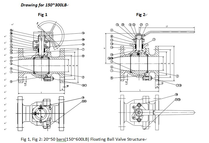
Please refer to Fig 1 and Fig 2 for valve structure.

4.1 Main Parts and Material
|
Fig 1 |
Fig 2 |
||
|
NO. |
Parts name |
NO. |
Parts name |
|
1 |
Body |
1 |
Body |
|
2 |
Closure |
2 |
Closure |
|
3 |
Ball |
3 |
Ball |
|
4 |
Yoke |
4 |
Gland flange |
|
5 |
Gland flange |
5 |
Level |
|
6 |
Seat ring |
6 |
Seat ring |
|
7 |
Stem |
7 |
Stem |
|
8 |
Gland |
8 |
Gland |
|
9 |
Gasket |
9 |
Gasket |
|
10 |
Packing set |
10 |
Steel ball |
|
11 |
Packing |
11 |
Packing set |
|
12 |
Packing |
12 |
Packing |
|
13 |
Packing |
13 |
Packing |
|
14 |
Thrust plate |
14 |
Packing |
|
15 |
Gear actuator |
15 |
Stop plate |
|
16 |
Stud |
16 |
Thrust plate |
|
17 |
Nut |
17 |
Stud |
|
18 |
Bolt |
18 |
Nut |
|
19 |
Bolt |
19 |
Bolt |
|
20 |
Stud |
20 |
Spring |
|
21 |
Spring |
21 |
Bolt |
|
22 |
Steel ball |
22 |
Retainer |
|
23 |
Rivet |
23 |
Washer |
|
24 |
Nameplate |
24 |
Rivet |
|
25 |
Nut |
25 |
Nameplate |
|
26 |
Butterfly spring |
|
|
|
27 |
Key |
|
|
|
28 |
Pin |
|
|
Table 5:Body material suitable for fluid and temperature range
|
|
ASTM A216-WCB |
ASTM A352-LCB |
ASTM A352-LCC |
ASTM A217-WC6 |
ASTM A217-WC9 |
ASTM A351-CF8 |
ASTM A351 CF8M |
ASTM A351-CF3 |
ASTM A351 – CF3M |
|
RECOMMENDED TEMPERATURE LIMITS |
-29~427 (T2-T6) EN13463- 2001 (E) |
-46~343 (T2~T6) EN13463- 2001 (E) |
-46~343 (T2~T6) EN13463- 2001 (E) |
-29~593 (T1~T6) EN13463- 2001 (E) |
-29~593 (T1~T6) EN13463- 2001 (E) |
-29~537 (T1~T6) EN13463- 2001 (E) |
-29~593 (T1~T6) EN13463- 2001 (E) |
-29~427 (T2~T6) EN13463- 2001 (E) |
-29~454 (T1~T6) EN13463-2001 (E) |
|
APPLICATION |
STEAM, WATER, OIL, VAPOR, GAS and GENERAL SERVICE |
LOW TEMPERATURE SERVICE STEAM, WATER, OIL, VAPOUR, GAS |
HIGH TEMPERATURE SERVICE STEAM, WATER, OIL VAPOUR, GAS |
HIGH and LOW TEMPERATURE SERVICE CORROSION RESISTANCE |
|||||
Note: where the process fluid is flammable/explosive, it must limit the working temperature of the pipeline system.
Table 6:Valve main parts and material for 150~800LB
|
Part name |
Materials (ASTM) |
||||||||
|
Body |
A216-WCB |
A216-LCB |
A216-LCC |
A216-WC6 |
A216-WC9 |
A351-CF8 |
A351-CF8M |
A351-CF3 |
A351CF3M |
|
Closure |
A216-WCB |
A216-LCB |
A216-LCC |
A216-WC6 |
A216-WC9 |
A351-CF8 |
A351-CF8M |
A351-CF3 |
A351CF3M |
|
Ball |
A105, F304, F316, A276 410 etc. |
||||||||
|
Yoke |
AISI 20-ZN |
||||||||
|
Gland flange |
A216-WCB |
A216-LCB |
A216-LCC |
A216-WC6 |
A216-WC9 |
A351-CF8 |
|||
|
Level |
1Cr18Ni9Ti (DN≤1”) or AISI 45 |
||||||||
|
Seat ring |
PTFE, PEEK, NYLON 1010 |
||||||||
|
Stem |
A105, F304, F316, A276 410 etc. |
||||||||
|
Gland |
A276 420 |
1Cr18Ni9Ti |
|||||||
|
Gasket |
Graphite or stainless steel winding gasket |
||||||||
|
Packing |
Graphite |
||||||||
|
Packing |
PTFE |
||||||||
|
Packing |
PTFE |
||||||||
|
Packing |
PTFE |
||||||||
|
Stop plate |
AISI 45-NI |
||||||||
|
Thrust plate |
PTFE |
||||||||
|
Steel plate |
1Cr18Ni9Ti |
||||||||
|
Spring |
1Cr18Ni9Ti |
||||||||
|
Stud |
A193-B7 |
A320-L7 / A320-L7M |
A193-B16 |
A193-B8 / A193-B8M |
|||||
|
Nut |
A194-2H |
A194-4 / A194-7M |
A194-4 |
A194-8 / A194-8M |
|||||
|
Bolt |
A193-B7 |
A320-L7 /A320-L7M |
A193-B16 |
A193-B8 / A193-B8M |
|||||
|
Butterfly spring |
50CrVA |
||||||||
|
Retainer |
Carbon Steel |
1Cr18Ni9Ti |
|||||||
|
Washer |
Carbon Steel |
1Cr18Ni9Ti |
|||||||
|
Key |
Carbon Steel |
1Cr18Ni9Ti |
|||||||
|
Pin |
Carbon Steel |
1Cr18Ni9Ti |
|||||||
|
Rivet |
Carbon Steel |
1Cr18Ni9Ti |
|||||||
|
Nameplate |
Stainless steel |
||||||||
4.2 Working Principle
The function of the ball valve is to cut off or put through the pipeline. When the ball drove by the wrench or other actuator, it rotates and the bore of ball superposition/perpendicular with the bore of body, the valve opens/closes.
4.3 Structure Description
4.3.1 This series uses packing seal structure. PTFE or NYLON is used as the seat ring material, PTFE or GRAPHITE is used as the stem packing material.
4.3.2 In the event of fire, when all the soft seals are damaged, ball valve have post-fire metal-to metal contact of all sealing areas such as:
Contact between ball and body;
Contact between stem and body;
Contact between coupling flanges of split body.
4.3.3 This series uses packing seal structure. PTFE or NYLON is used as the seat ring material, PTFE or GRAPHITE is used as the stem packing material.
4.3.4 Double “D” stem head design provides mounting of the lever handle always in parallel to the flow passage. Misalignment of the handle is thus presented.
4.3.5 The lower end of the stem is designed with an integral collar to be blowout-proof.
For more information, please contact:
ZHEJIANG TIANSHENG VALVE CO., LTD.
Linyang Industrial Zone,Wenzhou City,ZhejiangProvince. P. R. China
Tel: +86-577-67379608
E-mail:tsv@tsv.cn
We use cookies to enhance your browsing experience, serve personalized ads or content, and analyze our traffic. By clicking "Accept All", you consent to our use of cookies.

